HOW TO CONVERT A 165 REAR WHEEL HORSEPOWER 2.0 LITER ENGINE INTO A 2.2 LITER MONSTER
10/2004 UPDATE-SERIOUS PROBLEMS WITH THE PREVIOUS ENGINE BUILD
- After installing an HKS head gasket, and resurfacing both mating surfaces, the engine was producing a reliable 300RWHP at 1 BAR of boost. I drove it that way for 3000 miles, running it occasionally at the dragstrip, where it made two 12.9 second passes. On June 12, 2004, the car overheated at the 1400 foot summit of the Oregon Coast Range, resulting in a $170 tow back home. Another $170 tow to Torque Freaks, and an engine tear down later, we found out that the problem was not head gasket related. All this time, there was a hairline crack in one of the bores, that was causing the overheating problem. This means that the machine shop either didn't magnaflux the block, or missed the crack when they did. In addition to this, multiple other problems were found, including the cylinder wall clearance being too tight, resulting in the pistons being scuffed, and unuseable, dirt and metal fragments embedded in the main bearing caps, oil debris damage to the cams and cam journals...clearly Beaverton Auto Machine does not have a "clean room" and did not clean the parts while assembling the engine.
- I gathered up all of my parts and shipped them to Chris Katthage of Engine Logics, in the Houston, Texas area. Chris is an expert engine builder, specializing in the 3SGTE, and particularly, hybrid strokers. Chris informed me that the pistons could not be reused, and that his crank machinist had determined that the crank had been improperly machined, resulting in each cylinder having a different stroke, varying by up to twenty thousandths. The crank was also warped. Due to the amount the crank was out, it also was not reusable.(big suprise)
- I had Chris build me a new shortblock, using a 5S block and crank from a 1998 Toyota Camry, my Eagle rods, CP 9:1 CR forged pistons, and a TTe multilayer steel head gasket. He also ported and shimmed the oil pump for more flow and higher pressure, allowing high RPM operation of the engine, without risk of oil starvation. He refinished both mating surfaces to RA34, and assembled the long block. I have the engine back in the car, and am in the process of putting it through a 1000 mile break-in period, before installing the top feed rail, 880cc/min injectors, and heading to the dyno to tune for power.
DETAILS ON THE STOCK ENGINE
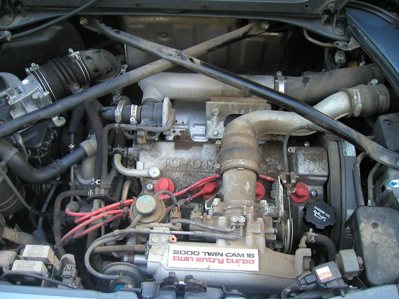
- The 1991-1995 U.S. Spec MR2 turbo came equipped with a dual overhead cam, 16 valve inline 4 cylinder engine which produced 200 horsepower and 200 foot-pounds of torque in its stock form. (Flywheel horsepower) Due to drive-train losses, about 165 horsepower is usually measured at the wheels. Stock boost specification is 7-11 PSI.
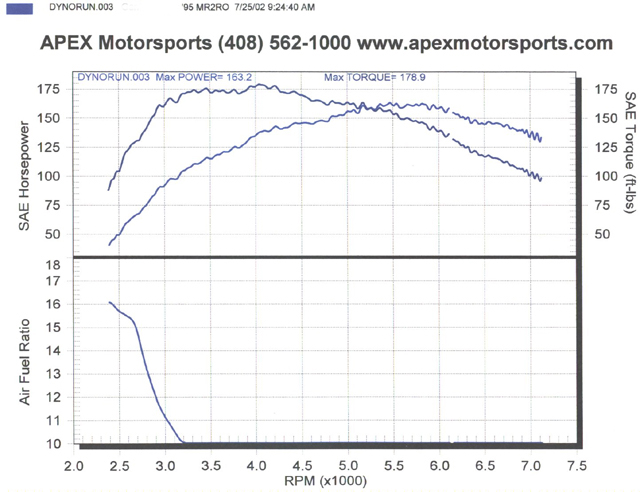
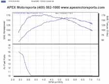
- Stock torque peak is 200 ft-lbs. @ 3200RPM (flywheel) If you examine the dyno graph below, you can see that this translates into almost 175 ft-lbs. of torque at the wheels at 3200RPM. Thus it is safe to draw the conclusion that an MR2 Turbo which has at least 175 ft-lbs to the wheels by 3200RPM can be characterized as having "stock spool" or "stock lag
Stock Engine:
 |
Stock Dyno Graph:
 |
WHY A STROKER? HOW?
- Its very hard to get much past 300 rear wheel horsepower without installing a large turbo, which causes you to sacrifice some spool, resulting in increased lag. One way to minimize the lag associated with a larger turbo is to increase the displacement of the engine.
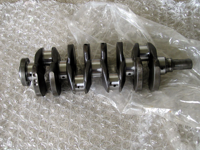
- There are two ways to increase the displacement: Boring out the cylinder diameter, and increasing the length of the stroke. The stock engine has an 86mm bore with an 86mm stroke. The 2.2 liter stroker engine will have 87mm forged pistons, resulting in a .040 overbore, with the crank from the 5SFE engine found in the naturally aspirated MR2, which increases the stroke to 91mm.
- The 5S crank has slightly larger rod journals than the 3S crank, so the rod journals are turned down on a lathe to the diameter of the 3S journals, allowing the 3S rods to be retained, or aftermarket 3S rods to be used. The crank is also cryogenically treated, for durability.
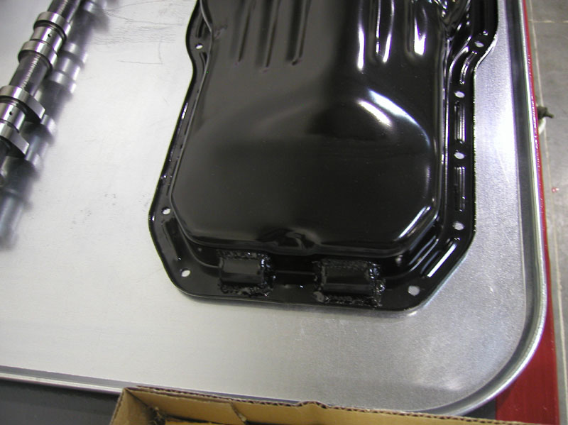
- A set of Eagle H beam rods are sourced for the project. The stock rods are very capable, and would be able to support the horsepower and torque increase, but the Eagle rods are almost 200 grams lighter per rod, reducing the rotating mass of the engine, while not sacrificing strength or reliability. ARP Rod bolts come standard with the Eagle rods, and are utilized in the project, along with ARP Head studs and Main studs. Two of the ARP main studs are slightly longer than the OEM fasteners. As a result, reliefs must be created in the stock oil pan to accommodate the longer studs.
PARTS, PARTS PART
Last month we talked about the stock 3S-GTE engine, its displacement, and how to get a 10% displacement increase. Some other components needed to finish the 2.2 liter bottom end are the OEM Toyota flywheel from the ST165 (1988-1989 Toyota Celica All Trac). This flywheel is the same size as the standard flywheel on a 91-95 MR2 Turbo engine (Gen 2 3SGTE) while having the same bolt pattern as the 5S-FE crank.
The flywheel is secured to the crank using the OEM 5S-FE flywheel bolts, which are the right thread pattern/size for the crank, while having very larger shoulders just under the bolt heads, in order to fully engage the holes through the flywheel. Using this flywheel allows you to use the various clutches that have been developed for high horsepower MR2 Turbos, instead of having to use a smaller clutch, designed for the 5S-FE.
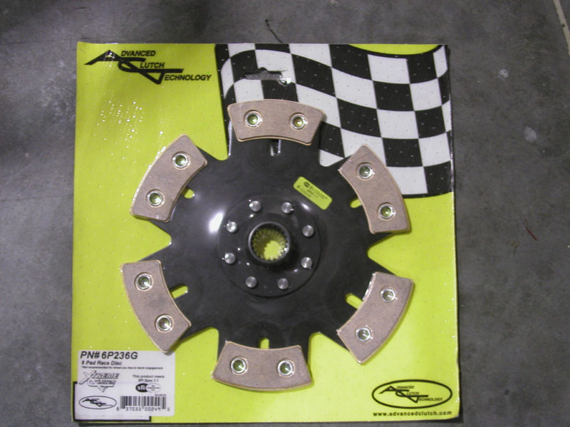
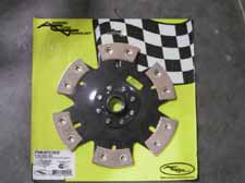
ACT 6 Puck clutch
 |
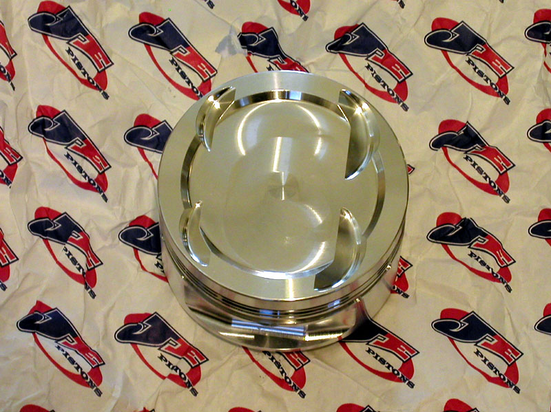
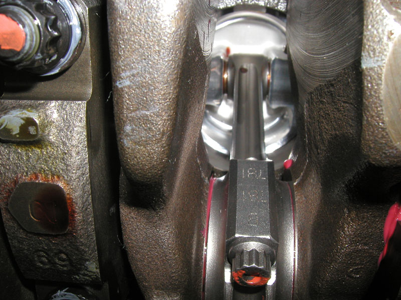
View of underside JE Piston / Eagle Rod
 |
HEAVY BREATHING
When you increase displacement, you also have to increase the engines ability to breathe. This is known as head work, and sometimes seems to be as much art as science.
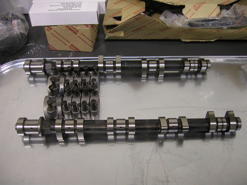
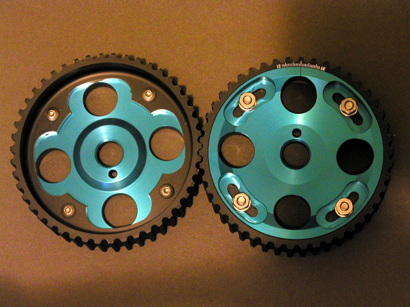
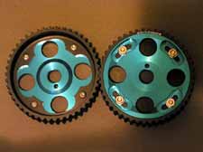
The goal of this buildup is to create a machine that drives easily and well on the street, with great low end torque. With these parameters in mind, I chose HKS 264 cams, for both intake, and exhaust. The cams will increase the lift and duration, which will allow more mixture to enter and more exhaust gases to exit during every valve opening, while still allowing the car to pass emissions, and maintain a reasonably smooth idle.. The 264 cams are matched with a set of Fidanza adjustable cam gears, which allow the cams to be properly degreed during installation, to HKSs exact specifications.
HKS 264 Cams
 |
Fidanza adjustable cam gears
 |
Other valve train components I sourced are Ferrea stainless steel valves, aluminum/titanium valve guides, locks, springs, and retainers. A 3 angle valve job was performed on the head, and the shimless valve buckets from the 2001-2004 MR2 Spyder were installed. The shimless buckets reduce valve train weight, while eliminating the possibility of a shim popping out, and causing havoc in the head.
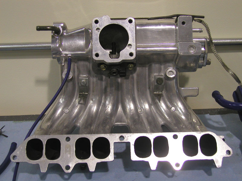
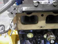
The head received a mild porting, mostly just removing casting marks and other obstructions to flow. The coolant passages around the #3 cylinder were enlarged slightly, since that cylinder tends to run a little hotter than the other 3. The TVIS (Toyota Variable Intake System) was removed, and a phenolic resin spacer was installed in its place. The purpose of this is twofold: the spacer will insulate the intake manifold from the head, preventing heat transfer to the manifold, and thus the intake charge, and in high horsepower applications, the TVIS can become a significant obstruction, even when open.
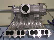
On milder engines, the TVIS should be retained, and the opening point controlled, to help decrease lag. The head was port matched to the spacer. The OEM intake manifold was sent out to Extrude Hone, to have the runners flow-matched, and the overall flow increased. In stock form, the #3 runner flows 13% more air than the other three. After the extrude hone process, the runners are all flow matched to within 3% of each other.
Resin Spacer / Port matching
 |
Extrude Honed intake manifold
 |
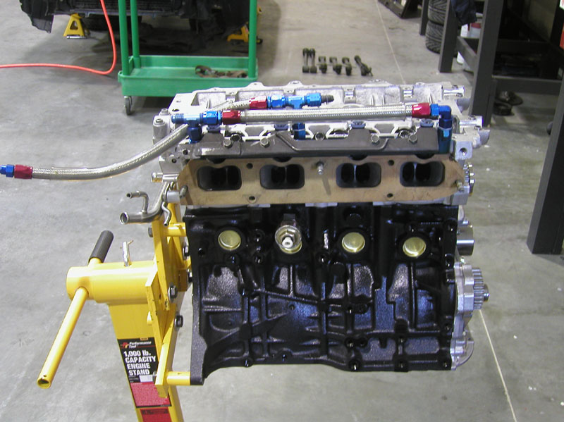
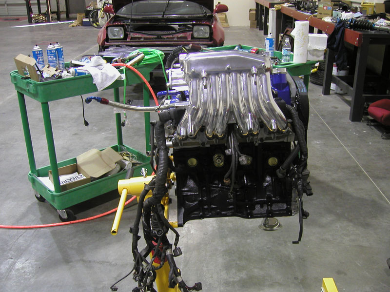
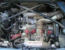
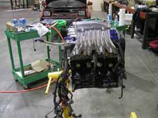
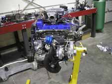
With all of these components and steps taken, the engine is really starting to take shape. Here are a couple of pictures of the engine as it starts to come together:
Intake manifold side
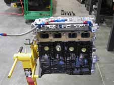 |
Exhaust manifold side
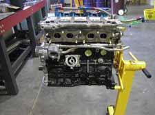 |
DETONATION, AND HOW TO AVOID IT
Last month we discussed how to get more flow from the head, to support the increased displacement. Now Id like to talk about one of the main enemies of a forced induction engine: detonation, which is also referred to as "knock", or "pinging". Detonation usually sounds like someone has a bunch of un-popped popcorn in a coffee can and is shaking it around. It can be caused by a variety of things, such as too much timing advance, too much boost, low fuel octane, inadequate intercooling, etc.
One of the easiest ways to help prevent detonation when building a forced induction engine is to lower the compression ratio. The gen 2 3S-GTE came with 8.8:1 compression ratio, which is quite high, even for some naturally aspirated engines. The Gen 3 3S-GTE which was never sold in any North American Toyota, had 8.5:1 compression. That engine makes about 45 more horsepower in stock form than the gen 2 engine, partially due to a better turbo, and increased boost. I decided to follow in Toyotas footsteps, and used 8.5:1 pistons in my stroker. This will allow me to run more boost, safely, than I could otherwise, all other things being equal.
Some people have considered RAISING the compression ratio, and simply running less boost. This will net better off-boost response from the car, but since the turbo is far more efficient at moving air than the pistons are, the on-boost power level will be reduced. With the advent of affordable, easy to install engine management systems, like the plug and play Hydra Nemesis, and the AEM plug and play EMS, this may change. People will be able to get away with running higher compression ratios by lowering the ignition timing advance, and thus retain the ability to run high boost on the engine.
Other things that can help prevent detonation are upgraded intercoolers, and water injection. I run the Spearco Racing air to air intercooler, which is a bolt-on intercooler that fits in the OEM side-mount location. Ive had my intercooler coated with a ceramic heat dispersant coating, to make it more efficient. The intercooler piping is a custom "one-off" by my company, KO Racing.
The water injection system I decided to go with is the Aquamist 1S, which is their most affordable system, at ~$450. It is normally activated by a pressure switch, which is adjustable. I have mine controlled by my engine management system, which allows me to activate it based on boost level AND RPM.
Spearco Air to Air Intercooler
 |
Aquamist pump
 |
HEAD GASKET
I initially sourced a TRD (Toyota Racing Development) metal head gasket for this engine. On the initial start, the head gasket leaked, requiring the engine to be pulled back out after only a short period of operation. It was determined that the finish on the mating surfaces of the head and block was incorrect, so they went back to the machine shop to be resurfaced. Not wanting to take any chances, I decided to source an HKS 1.0mm head gasket, which is known for its ability to hold high boost without leaking, as long as the mating surfaces are finished to HKSs specifications. The head is bolted down using ARP head studs, torqued to 75 foot-pounds.
Here are some more pictures of the engine, nearly complete:
Intake manifold installed
 |
Valve cover installed
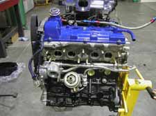 |
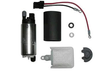
FUEL REQUIREMENTS
The stock fuel system on an MR2 turbo is fairly robust, and will support up to 280 rear wheel horsepower before it starts going lean at higher engine RPM. At this point, it becomes necessary to swap in a fuel pump that can flow more, like the pump from the MKIV Twin Turbo Supra. Another good pump is the Walbro 255 high pressure pump. My car has had the Supra pump installed for nearly as long as Ive owned it, since I knew that my horsepower goal exceeded the stock pumps capabilities.
The next thing to look at is the fuel rail. The stock fuel system is a sequential side feed rail, which means that the fuel comes in at one end of the rail, and passes through each injector in sequence, until it reaches the #4 cylinder. The stock rail has a standard 1:1 rising rate fuel pressure regulator on it. This setup inevitably results in the #3 and #4 injectors being starved of fuel, compared to the #1 and #2 injectors. That resulted in a popular mod, which is known as a DFFR (Dual Feed Fuel Rail). The rail is fed from both ends, and the interior bore of the rail is increased, allowing more fuel to flow to each injector, and virtually eliminating the fuel starvation problem. An aftermarket adjustable fuel pressure regulator is typically installed at the same time as the DFFR, to allow adjustment of the base, or idle, fuel pressure.
Walbro Fuel Pump
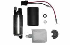 |
Dual Feed Fuel Rail
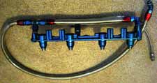 |
One other down side of the side feed injectors, is that they are not widely used, which means they are very expensive, when compared to a top feed injector. By the time you spend the money to modify your fuel rail to dual feed, and buy the larger side feed injectors, its easy to spend more money than a top feed fuel rail conversion, with the less expensive top feed injectors. My present fuel rail and injectors (550cc/min injectors from a MKIV Supra TT) will limit me to approximately 350 rear wheel horsepower, with the injectors at 90% duty cycle. Since my goal is higher than that, I will be swapping in a KO Racing top feed rail with 880cc/min top feed injectors, before raising boost, and tuning the car for power.
THE TURBOCHARGER
With all of the time, work, planning, and money spent getting this engine ready to make big power, its time to choose the turbo kit Ill be using. One of the most important factors when choosing a turbocharger is SIZE. Proper sizing of the turbo to the engine is critical to achieve a wide power band, with a nice, fat torque curve. There is an increasing trend in the MR2 community, and the import community as a whole, to look ONLY at peak rear wheel horsepower numbers when choosing a turbo. This results in a lot of unhappy people, when they get their turbo kit after months and months of saving, and waiting, and they dont hit full boost until past 4000RPM. Since the stock rev limiter is at 7250, this will yield a very narrow power band, especially if you are running the stock cams, which limit peak horsepower to about 6000RPM. A car like this is not very much fun to drive, except at the track or drag strip, since you are constantly shifting gears to try to keep the car in its power band, and spending a lot of time waiting for the turbo to spool up. The answer to this is the KO Racing Street Brawler turbo kit.
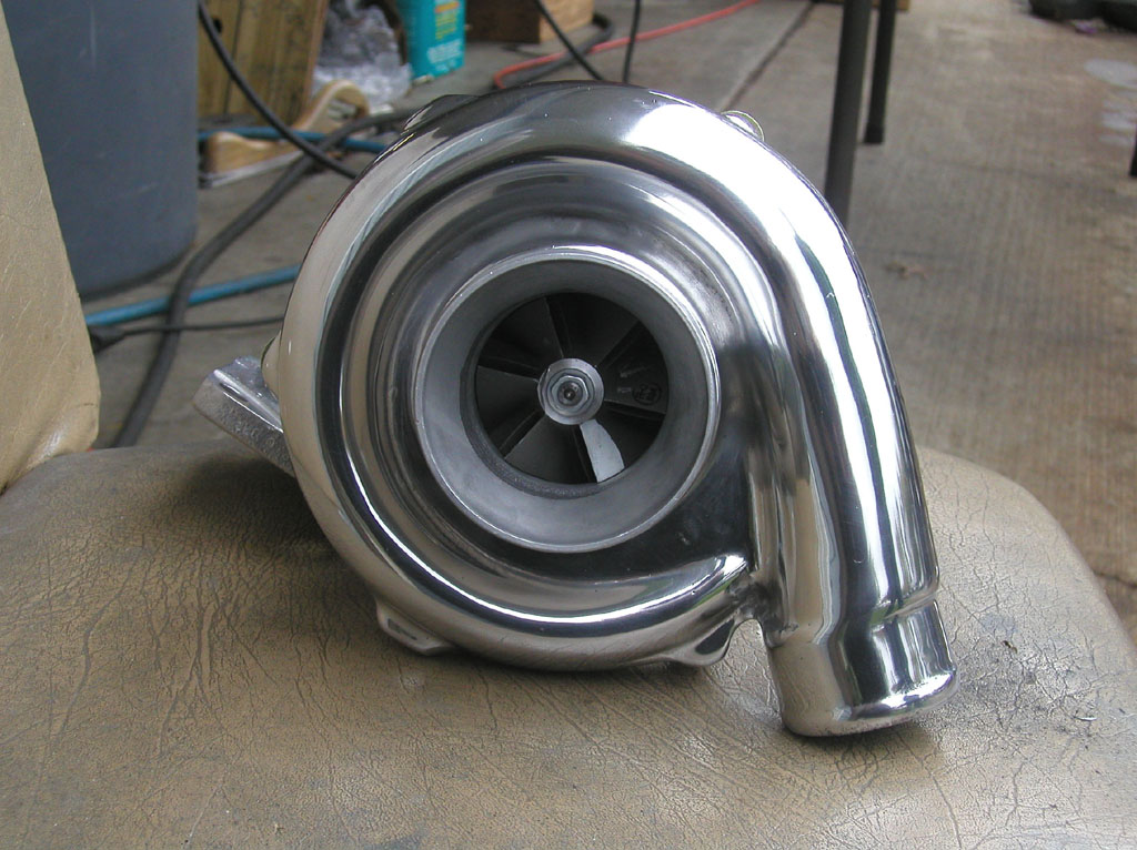
Garrett T3/T4 Turbo
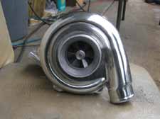 |
KO Racing Street Brawler Kit
 |
The kit is designed around the Garrett T3/T4 turbocharger, which uses the smaller turbine section from a T3 turbo for quick spool, with the larger compressor from a T4 for big flow. Its also referred to as a hybrid turbo. The nice thing about this turbo, is that you can completely change its spool and flow characteristics, simply by ordering a different size turbine, and/or compressor. Its also quite inexpensive, compared to other turbochargers.
Weve experimented with several different turbine and compressor sizes for the Street Brawler, and for the 2.0 liter MR2, weve found that the TO4E-46 trim compressor is the best for a street-driven car, paired with either the .48 stage 3 or the .63 stage 3 turbine, depending on what the driver prefers: minimal lag at any cost, or moderate (better than stock) lag, with a little more high RPM potential. Since my engine has a displacement increase, along with plenty of head work, I decided to source a .63 stage 3 turbine, with a TO4E-50 compressor. This combination is on its efficiency island to about 26-28 PSI, which is more boost than I plan to run. We plan to do further testing of this turbo on a 2.0 liter car, to see what the spool and horsepower potential is in that application.
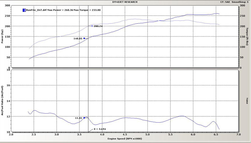
With the engine re-installed in the car, it was time to put the car on the dyno for the initial tune, which would be used to break in the engine for 1000 miles. I have the boost controller turned off, which has the car running at 10PSI (maximum), which is the spring pressure for the Tial 38mm wastegate that I am running. The engine and turbo kit are performing incredibly well at 10 PSI, putting down 260 rear wheel horsepower, and 233 foot-pounds of torque.
10 PSI Dyno Plot
 |
THE BRAINS OF THE OPERATION
Ive talked about upgrading the fuel system, and the turbocharger, and just about every other aspect of getting reliable performance out of this engine. Whats left? The most important part, engine management and ignition. I chose the SDR Maxi "SparkDog" engine management system to run my engine. As available from www.mrcontrols.com, it is a plug and play application for the MR2 Turbo, with no hacking into the stock wiring harness required. The EMS arrives with a base map loaded, that will start, idle, and run the car off-boost, allowing you to drive it to the dyno for tuning. From the time the package arrives, until you are turning the key to start the car, will take 1-2 hours for most people. My car started up on the first try. The SparkDog has since been superceded by the Hydra Nemesis, which brings the same plug and play compatibility, with a much better list of features, and a 32x32 map. Ill likely be upgrading to the Nemesis in the near future.
SparkDog w/ PnP Box
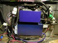 |
MSD6A Ignition
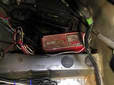 |
When running high boost, it becomes increasingly difficult for the stock ignition to light off the mixture in the cylinders. The massive amount of boost being forced into the engine can literally blow out the spark, like a candle on a birthday cake. To prevent this from happening, I installed an MSD 6A, with an HVC "Blaster" coil. The MSD is fired by one of the auxiliary outputs on the SparkDog.
PRELIMINARY RESULTS
With the engine re-installed in the car, it was time to put the car on the dyno for the initial tune, which would be used to break in the engine for 1000 miles. I have the boost controller turned off, which has the car running at 10PSI (maximum), which is the spring pressure for the Tial 38mm wastegate that I am running. The engine and turbo kit are performing incredibly well at 10 PSI, putting down 260 rear wheel horsepower, and 233 foot-pounds of torque.
10 PSI Dyno Plot
|
I eventually plan to run about 20PSI on this engine, and expect to see 360-400 rear wheel horsepower at that boost level. That will be more than sufficient to carry the car deep into the 11 second range in the quarter mile. Thats also a bit much to run on the street, unless you like replacing tires monthly. I plan to detune the car to about 300RWHP for street driving, and run high boost at the track/drag strip while running dedicated track tires and wheels. Look for new dyno plots, and maybe even some time slips in part 6.
THE VENDORS
None of this would have been possible without the help of several key shops. Here is a list of the primary modifications, and where I obtained them:
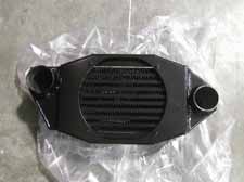
Street Brawler turbo kit, TKO Exhaust, custom intake, EGR block off plates, port matching:
KO Racing (Hillsboro, OR)
Eagle Rods, Custom Crank, ST165 Flywheel, Extrude Honed intake manifold, Aquamist 1S Water Injection:
ATS Racing (Richardson, TX)
JE Pistons, ARP Fasteners, Ferrea Valve train components, ACT 6 puck racing clutch, Spearco air to air intercooler:
HP Motoring (Miami, FL)
3.933 final drive parts, fluids, gaskets, and many other OEM parts:
Royal Moore Toyota (Hillsboro, OR)
SDR Maxi "SparkDog" Engine Management System and plug and play interface box:
MR Controls (San Jose, CA)
HKS 264 Cams, Denso Iridium IK22 spark pugs, Greddy Type R BOV
Horsepower Freaks (Portland, OR)
Removal and Reinstallation of the engine, disassembly and reassembly, shimless bucket conversion, head porting, final drive modification, cam degreeing, as well as street and dyno tuning
Torque Freaks (Portland, OR)
HKS 1.0mm metal head gasket
MVP Motorsports (Fort Worth, TX)
RAISING BOOST
After 1000 miles of breaking in the engine, with about 6 oil changes along the way, it was time to raise the boost on this engine, and get a power tune. The car was previously putting down 260 rear wheel horsepower and 233 foot pounds of torque at the minimum boost level, which is 10PSI.
10 PSI Dyno Plot
|
I brought the car back to Torque Freaks, where the ARP head studs were re-torqued, and a compression check was performed. The engine had 185PSI in all four cylinders, which is right on target for this engine, with 8.5:1 compression ratio pistons. All systems were go, it was time to raise boost and see what this engine could put down.
UNEXPECTED DELAY
I arrived at Torque Freaks Monday afternoon for the tuning session. That's when we hit a snag. The car made two baseline pulls at the previous power level, then started pulling timing advance under boost, even though no knock was being detected. We contacted MR Controls, who gave us several suggestions, to no avail. We decided to postpone the tuning until the next day, when we could install an extra SDR EMS that was at my shop, across town. With the other EMS, the timing problem mysteriously disappeared. The problem with the EMS turned out to be a minor grounding issue with the IAT sensor, that was easily corrected, once we realized what was wrong.
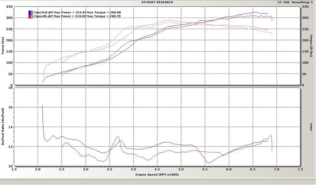
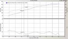
15 PSI Dyno Plot 3rd and 4th gears
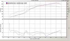 |
With that problem cleared up, we were able to raise boost to 15PSI, where the car is making 323 rear wheel horsepower, and 288 foot pounds of rear wheel torque. We are running out of injector at 15PSI/6500RPM, so weve temporarily set the Rev limit there, until product development on a KO Racing Top Feed Fuel Rail with 880cc/minute injectors can be completed. At that time, I will be upgrading the down pipe and exhaust to 3 inch diameter piping, and upgrading the EMS to the Hydra Nemesis. We will then retune the car for 20PSI, which will hopefully yield between 380 and 400 rear wheel horsepower.
|