1 container of anti-seize rated at 1800 degrees or higher.
NOTE: In the following instructions, when a bolt is referred to as a "14mm" for example, this indicates the size of the wrench required to remove it, not the shank size as is standard.
Click any image for a larger size.
Ensure that the rear of the car is elevated and properly supported with jack stands or ramps to allow access to the primary catalytic converter, but not so high that you can't reach into the turbo area of the engine bay from the top (about 11" of clearance from the cross member to the ground), and that the car has properly cooled down ~45 minutes.
Step 1:
The first thing you need to do is to spray all visible fasteners with PB blaster or equivalent bolt loosener and allow it to soak (like 1 day if you have time, or 30 minutes if not) on both the catalytic converter and turbine outlet elbow.
Step 2:
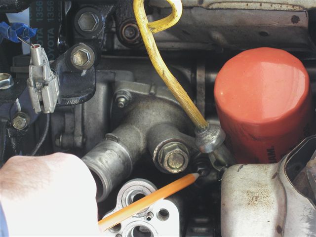
Remove the oil filter being careful to not spill oil out of it (as much as you can since it's mounted upside down), and remove the 12mm head bolt holding the oil dipstick in place (just let the dipstick flop around).
Step 3:
Remove the turbo to intercooler cast aluminum pipe and blow off valve as a unit by loosening the 10mm fasteners on the hose clamps and removing the pinch clamp from the boost/vacuum line that runs from the area near the distributor cap to the blow off valve.
Step 4:
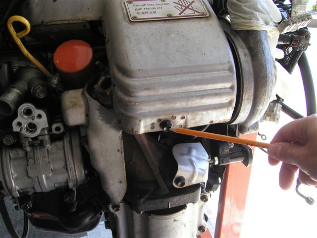
Remove the 3 12mm bolts holding the turbocharger heat shield in place (the one with the "Caution: HOT" written on it) and remove the heat shield. One is down on the side of the heat shield toward the firewall out of plain view -- but you should be able to get a combination wrench on it.
Step 5:
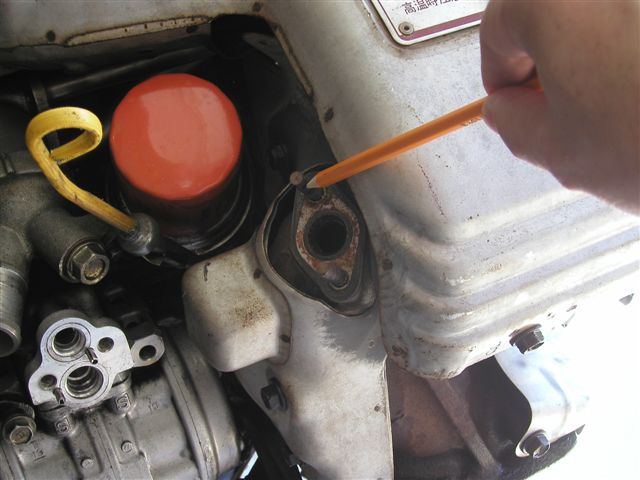
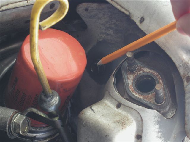
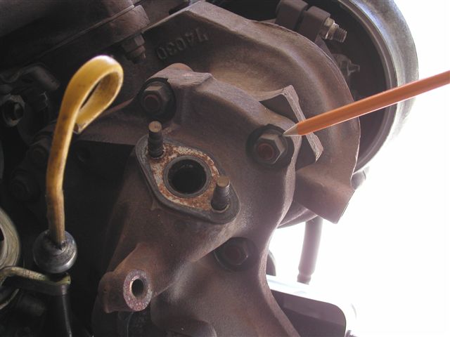
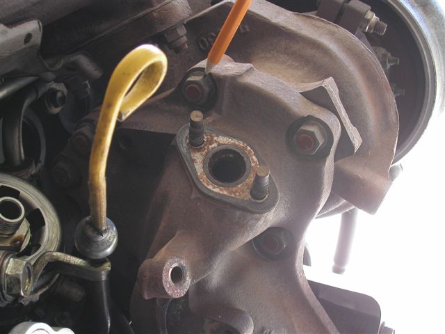
Remove the 2 12mm nuts holding the oxygen sensor in place and remove the oxygen sensor being very careful to not bang the oxygen sensor into anything as it is easily damaged. Retain the stock oxygen sensor gasket for reuse, or if it's damaged, you can order a new one from toyota (part number 17166-88381).
Step 6:
Remove the 3 12mm bolts holding the turbine outlet elbow heat shield onto the elbow (or you can't get to the turbine flange nuts). The top 2 are easy and in plain view. The bottom one requires a 3" extension and a standard depth socket.
Step 7:
Spray the turbine flange nuts with PB Blaster or equivalent and move to the underside of the car.
Step 8:
Remove the small plastic underbody pan that is directly below the catalytic converter (there are 6 10mm head fasteners -- note that one has coarse threads and threads into plastic and not metal).
Step 9:
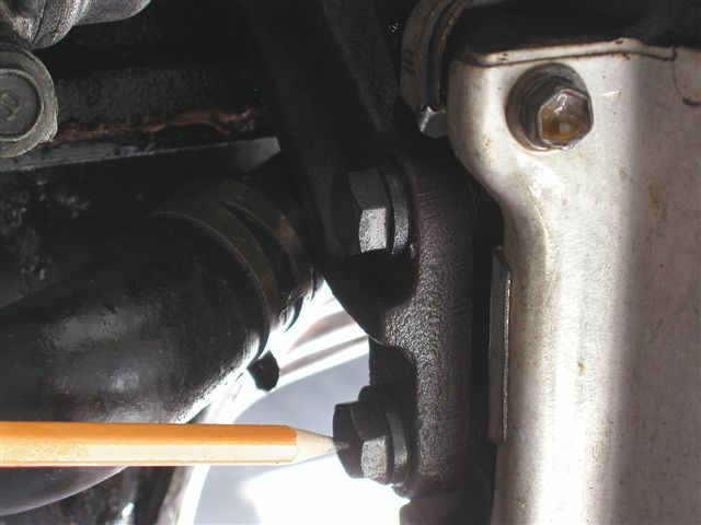
Remove the 3 14mm head nuts that fasten the b-pipe to the catalytic converter studs. These are likely to be seized up (good ol' PB Blaster).
Step 10:
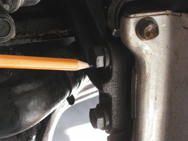
Remove the 3 14mm head bolts that fasten the stays to the sides of the catalytic converter.
Step 11:
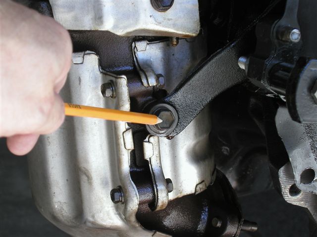
Remove the engine to transmission brace (triangular piece that has one 14mm bolt into the engine, and 2 14mm bolts into the transmission bell housing. One of the two transmission side bolts goes into the brace, and one goes into the transmission -- so from opposite sides.
Step 12:
Loosen the cat mounting stay bolts into the engine on the passenger's side stay. This will require a 3" extension and probably a long reach from the top as you can't see the fastener from the bottom. Once one of them (there are two) is broken loose, pry the stay away from the cat about 0.2".
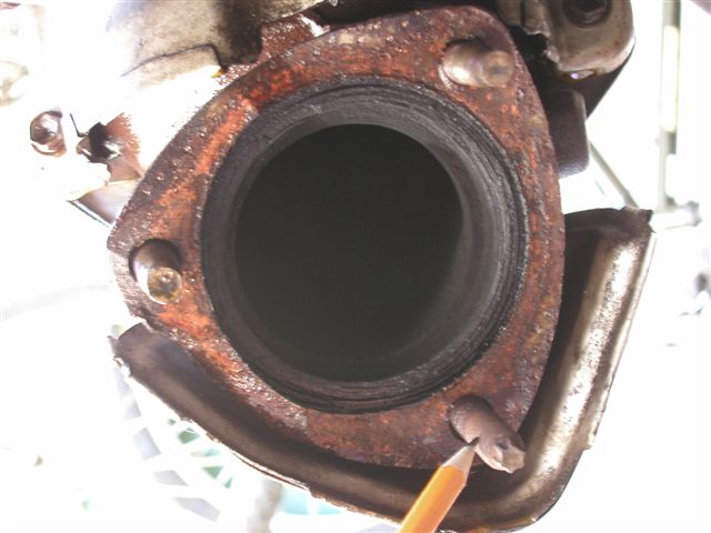
Step 13:
Remove the 3 12mm bolts and 2 12mm nuts (make sure these have soaked with pb blaster first) that hold the primary cat to the elbow. It's a good idea to put one nut back on to a stud a few threads to keep the cat from falling when the last bolt is pulled out. Be carefull when pulling the last fastener, as the cat may drop and it is *heavy*.
Step 14:
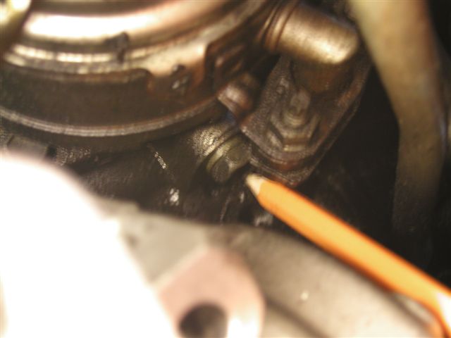
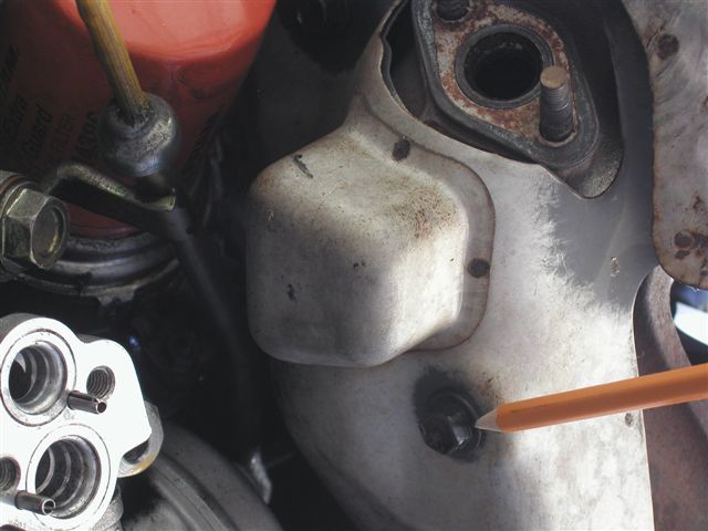
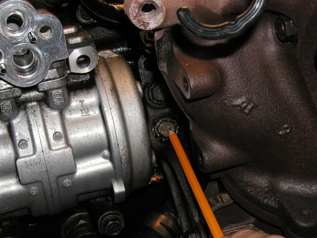
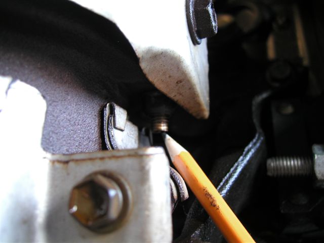
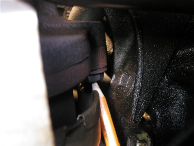
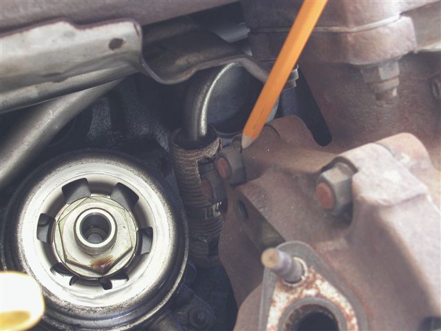
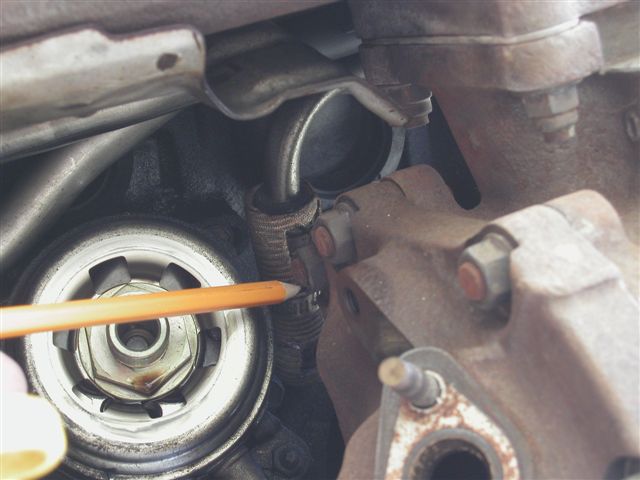
Remove the 12mm bolt down on the side of the oil cooler (where the oil filter mounts). Once the bolt is out, go back up top.
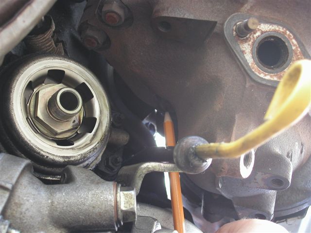
Step 15:
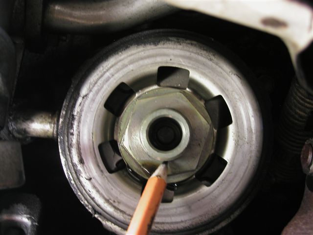
Remove the 30mm stud that holds the oil cooler in place (this is where the oil filter screws on). Be careful to not allow any foreign particles to enter into the oil system through this location (keep it covered with a clean rag).
Step 16:
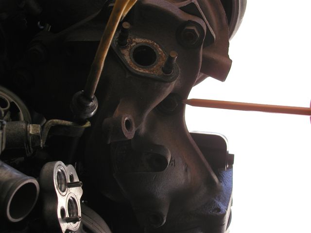
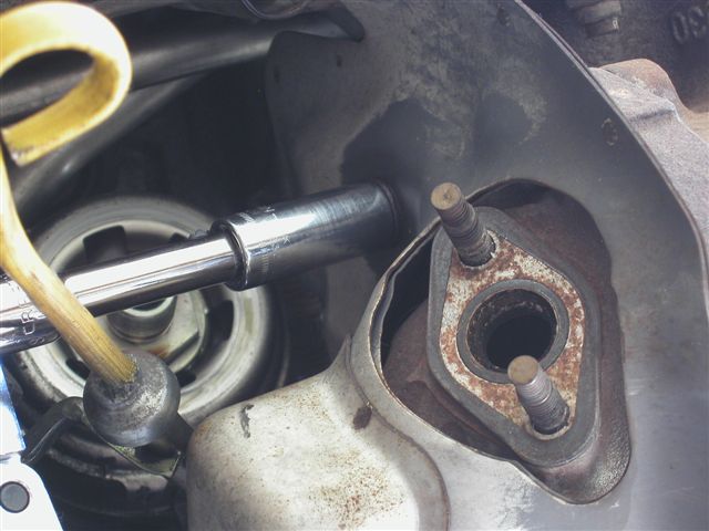
With the oil cooler loose, remove the 6 14mm nuts that hold the turbine outlet elbow to the turbine (7 nuts for a 3rd Gen). Be careful here to not round any nuts, as if you do, it means pulling the whole turbo/manifold/elbow assembly. Once the nuts are off, pull the turbine outlet elbow. There should be just enough room with the oil cooler loose. If your turbo is a CT20b, remove the 1 extra stud on the top side of the turbine exit that is not in the downpipe flange.
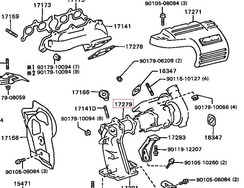
Step 17:
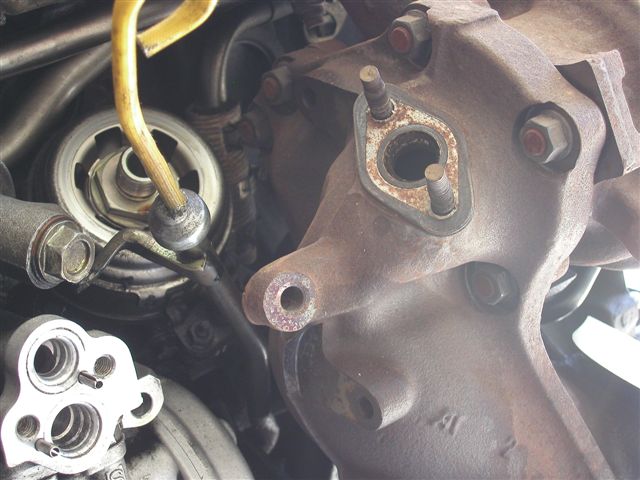
Inspect the turbine gasket to determine it's reuseability. If it is in poor shape, you can order one from toyota (part number 17279-88381).
Step 18:
Remove the 2 cat mounting stays by removing the 4 14mm bolts holding them to the block.
Step 19:
Reinstall the triangular support bracket that goes from the transmission bell housing to the engine block.
Step 20:
Time for a break and to assess the situation.
- Are there any broken studs/bolts? -- If so, this is the time to go to the hardware store for replacements -- unless they are the ones replaced by the hardware provided with the downpipe.
- Are there any studs that backed out with the nut? -- the use of a vise and a proper stud installer/remover should make this an easy chore (with some pb blaster of course!).
- Do you have all the gaskets you need? -- If not, order the ones you need, and suffer with your car down because you didn't order them before hand.
- If you are going to the hardware store anyway....
- Get some shorter studs for the turbine outlet (approx .1" shorter would be perfect to avoid having to pull the oil cooler when playing with the downpipe in the future.
- Get some anti-seize rated at 1800 deg F or higher (cause you forgot to get it before).
- Get some nice tool to reward your hard work :-)
Step 21:
Use anti-seize to coat the threads of the studs in the turbocharger.
Step 22:
Install the turbine outlet gasket onto the turbocharger, and install the KORacing downpipe.
Step 23:
Install 4 14mm nuts onto the turbine studs (the top 4). Be sure to leave the nut off that is second closest to the block on the top side to allow access to the nut that is nearest the engine block. This nut can only be tightened by use of the open end of a combination wrench, and as such, will not be able to be tightened as tight as the others. Once that nut is tight (snug the far 2 on the top before tightening this one), then install the last nut on the top, tighten them all, and go underneath the car.
Step 24:
Install the 12mm bolt into the engine oil cooler but *DO NOT TIGHTEN*. Also install the 12mm bolt into the dipstick tube (you can tighten this one).
Step 25:
Install 2 14mm nuts onto the bottom two turbine studs. Check for clearance between the firewall heat shield and the downpipe -- if it looks like it may rub, bend the heat shield with a large flat head screwdriver, then go back up top.
Step 26:
Install the 30mm oil filter mounting stud -- BE VERY CAREFUL -- as it is very easy to cross thread this piece (like if you tightened the 12mm bolt in the side of it). Be certain that this is threading correctly before tightening it down. A little extra time and care here will go a long way if it means you don't have to remove the aluminum part that this is threading into.
Step 27:
Install the oil filter, and 02 sensor gasket.
Step 28:
Install the 02 sensor and the 2 12mm nuts that hold it down. Now go under the car.
Step 29:
NOW tighten the 12mm nut into the side of the engine oil cooler. (Extensions and u-joints come in handy here)
Step 30:
Install the downpipe support bracket (Click here for more detailed instructions), b-pipe connection gasket, and the b-pipe using the stainless 3/8" hardware provided with the downpipe.
Step 31:
Install the plastic underbody pan with the 6 10mm bolts (puting the coarse thread one in its proper location). You are now done under the car.
Step 32:
Install the turbo heat shield and the 3 12mm bolts that hold it on.
Step 33:
Install the turbo to intercooler cast aluminum pipe and BOV assembly and tighten the clamps with a 10mm socket. Be sure to remount the boost/vacuum line to the line near the distributor with the pinch clamp, and connect the BOV vent hose if you are venting back to the intake.
Step 34:
Install the strut tower brace with the 2 14mm nuts and 2 14mm bolts.
Step 35:
Now ENJOY!
Final Notes:
- Boost pressure is likely to be higher due to the reduced backpressure, so adjust your boost controller accordingly.
- It is always a good idea to retighten all the bolts once the vehicle has been driven at operating temperature, then allowed to cool, but the critical ones are the 6 14mm turbine outlet nuts. Be sure to re-tighten these a day or two after the install.
- Boost creep can occur with very free flowing systems (clipped turbines and very free flowing exhausts), and may require you to port your wastegate to control boost.
- PLEASE NOTE: if you experience the inability to control boost (a sharp spike in boost) the first thing you should check is to make sure the wastegate is opening properly. If it is binding against the downpipe or turbo, use a flat blade screwdriver to gently pry the actuator arm away from the side of the turbo just enough to clear the downpipe flange and turbo.
- Thank you for purchasing a KORacing downpipe and I hope you enjoy it as much as I enjoyed making it for you.

